3 August 2020

Linux Mint - The Struggle Continues...

I thought I'd attempt to get at least one new blog entry penned for 2020, even though given the farcical 'lock-down' we've been subjected to over the last few months, and the long stretches of idleness concerned, this ought to have been one of my most productive blogging periods.  Evidently not!  About the only thing of note that I seem to have achieved during lock-down, was the completion of the 2 RTC units that I'd been promising myself for decades that I'd build.  But I'll leave that as an addendum for the blog entry in question.  Besides that, I've seemed to mostly spend my time watching movies or sitcoms, to the point where I'm now sick & tired of television.  Anyway, forgive my little preamble, on to the topic for consideration.

I'm still using Linux Mint 17.3 as my main OS, despite the fact that it has been EOL'ed for at least a year now.  I gave Mint 19.1 a go about a year ago and was initially enthusiastic.  This proved to be short-lived however when I realised that compared to 17.3, it was a bit of a piggy as far as memory was concerned.  As my main computer is still my old Dell laptop - and shall remain so until either it or I depart this realm - I am somewhat constrained by the fact that although the machine has two 2gig SODIMMs fitted, the stupid hardware is limited to using only 2.5gig of this.  I was so peeved when I discovered this (about a decade ago, when I upgraded its memory!) and never would have bought the laptop had I been aware of the fact at the time.

Anyway, as a result, I decided instead to hold off until the next Mint release.  This I only got round to trying a week or two ago - or would have, had it even been available!  You see, the Mint Developers have thought it prudent to drop 32-bit support from Mint 20 onwards, at least with its Ubuntu-based releases.  Instead, what they have added is 32/64-bit versions that are Debian-based, named LMDE 4, in case, and I quote, "Ubuntu were ever to disappear" - which sounds a bit ominous for Ubuntu's future prospects...

So one download of LMDE later, I was happy to discover that it installed & ran without issue.  Initially anyway.  What was soon apparent was that the Nouveau graphics drivers didn't work properly, often only scrolling part of the screen when browsing with Firefox.  It also transpired that the 'Driver Manager' app was no longer available, robbing me of the standard means of installing native Nvidia drivers!  This was unacceptable.  I then proceeded to waste days trying to install manually, driver versions downloaded from Nvidia's site, all to no avail - LMDE seems an impenetrable maze to Nvidia's old installers.

And there it lay, until I decided a day or so ago to give Mint 19.1 another go, more as a last resort than anything else.  On the plus-side, after playing with it for a few days now, Nouveau seems to work well, no glitches so far at any rate.  What had me cursing and swearing yet again at the Mint Developers was the realisation that once more, those idiots had not bothered to fix the audio-preview in the Caja file manager.  What they had done, yet again, was to disable audio-previews by default, in the hope that most users wouldn't notice the bug!  This kind of laziness is maddening to me.  A previous post here will recall the fact that this bug has been an unwanted addition of Mint-Mate releases at least as far back as version 17.1.

Given the amount of time & energy I had spent re-building the various buggy packages from Mate's source-code, I was more than reluctant at the idea of a repeat performance, but persevere I did.  And it proved surprisingly easy this time around!  One huge plus I noticed regarded the compiler.  Prior to this, issuing a './configure' would find the script stopping at each & every dependency issue that it encountered.  This resulted in my having, after resolving the highlighted dependency issue, to re-issue another './configure' - and again & again & again, often dozens of times, until all the dependencies had been resolved - which was soul-destroying.  Now what happens, after the first './configure', ALL missing dependencies, not just the first one encountered, are listed as packages "not found", which allows you to resolve all of the dependency issues in one go.

I was also delighted to find that after building the needed packages (caja-common & caja-extensions) and removing the 'broken' caja-common (which automatically removes Caja, as well as other packages that would conflict with the new build's installation), the new packages installed & worked without a hitch!  All that's needed is to add a Home Folder icon to the Panel to allow a one-click opening of Caja - just drag & drop the Home Folder onto the desktop to there, or navigate to Caja via Menu->System Tools, right-click on Caja and select 'Add to panel'.  Once old Caja has been uninstalled and its executable 'killed' using System Monitor, all that's left is to re-install 'mate-control-center' and fire up 'new Caja' via its panel icon.  In short, it works, no more Caja locking up during audio previews.  I'll include the built packages below, more for my own future use than anything else.


Right now I'm writing this on Mint 19.1, listening to some background music and everything seems to be running fine.  The memory problem hasn't gone away by any means - presently, with just Firefox and Streamripstar running, 2.3gig of my 2.5gig of memory is being used, with swap also starting to be impinged upon. 

Will this prove usable, or will I end up back with Mint 17.3? - only time will tell. 

Edit:
After posting above about the memory limitation of my old Dell XPSM1210 laptop, it got me thinking.  On the one hand, I was 99% certain of my facts - that the laptop had a limitation on the maximum amount of memory that the hardware could work with, 2.5Gig, which was well below the the 4gig limit imposed by 32-bit hardware.  On the other hand, this 2.5gig seemed an almost arbitrarily chosen number, which didn't make sense, so I went looking for confirmation of my long-held belief - and couldn't find any!  But I was certain that I had bought two 2gig SODIMMs when I did the memory upgrade, but was disgusted to discover that only 2.5gig was available to the user when it was installed.  I therefore removed one, replacing it with a 512Meg SODIMM instead.  This is my recollection of events anyway - I can't actually find the second SODIMM that I thought I'd bought!  That was more than 10 years ago. [Did a little checking, (re)discovered that Amazon keeps a long purchase history and that I bought just ONE 2Gig SODIMM, and it was 8.5 years ago, not 10+ - so wrong on both counts!].
 
Well, I was gifted an old HP laptop, minus PSU or working battery pack, about 4 years ago, and which I think I've already commented on in another post.  Long story short, after letting it gather dust for 6-9 months, I finally got a cheap Chinese PSU, powered it up and left it on a soak-test for 24 hours - which promptly killed it, or at least the Nvidia graphics part of it.  What it does have though is 4gig of SODIMM memory, that is Dell-compatible, and which for the first time, I've tried with it.
 
And yes, I was flabbergasted to discover on booting the Dell that I now have gone from having just 2.5gig, to having over 3.2gig of memory available to the user!!!  How could it have taken 10 years for the penny to drop!  Though I should be elated (and am a bit), what's bugging me now is the almost 800meg of memory that's 'unavailable' with 4gig installed, whereas with 2.5gig installed, all of that is available to the user.   The BIOS informs me that this 800meg has been allocated to the system, but nothing is allocated when 2.5gig is installed - so no doubt it's just using the top end of the address-space to map hardware to, with the 800meg left blowing in the wind.  Yep, always moaning, my glass is always half-empty.

Edit2:
Haha, seems I'm on a roll of sorts today.  The HP laptop that donated its memory to the Dell seems to have got a reprieve of sorts.  The graphics problems with these HP laptops is well known.  Despite the exorbitant prices HP charges, they are responsible for some really shoddy designs when it comes to cooling.  This problem effects multiple laptop's of theirs from what I've read,  so it's not a case of my being gifted a dud.  Anyway, what happens is, since the ineffectual cooling employed is incapable of cooling the GPU chip while under load, it literally cooks itself to death, with the soldered BGA contacts melting, and going open-circuit.  What the user ends up with at startup is, a blank screen accompanied by an  annoying Beeping.  Despite multiple past attempts at reflowing the Nvidia chip in question, it always reverted back to the beeping/blank screen.  Until tonight!  It's been running for a couple of hours, right now, playing a movie full-screen, without a bother so far!  This is only the second time I've witnessed it behaving 'normally', the first time obviously having been when I first powered it up.

Wow, all for naught, this thing really knows how to toy with me - after a few hours running perfectly, with the GPU sitting at around 60DegC the whole time, (normal for badly-designed laptops - my 14 year-old Dell, running 24/7 from new, never goes below 50DegC, often well exceeding 60DegC under load), the screen just goes blank.  Pulling the plug and powering it back up, it now exhibits a new behaviour - gone is the infernal beeping, the screen is just remaining blank, but with back light illumination.  I tried it again this morning and it powered up normally, but only remaining so for a few minutes before the screen went black again.

Well, I'm done with it, that thing goes into the bin next week, before garbage day.  I've sweated bullets for that piece of HP crap.  It could only have been worse had I spent money on it, never mind having bought it new.  Anyone considering buying 'prestige' brands such as HP should really do a little research into the quality/reliability of the junk that these clowns produce.  Add to that, this POS company uses 'white-lists' to decide what user hardware upgrades are allowable - anything not on the list is instantly black-listed.  Since HP can't foretell the future, the user is forever prevented from adding 'current-hardware' add-ons.  I discovered this when I tried upgrading the pissy 54Mb/s wireless card that came with this laptop, to something more current - all were black-listed, cited as not having been approved by HP.  Well, Good Riddance to HP.

At least I'm left with 4gig of ram and a usable 100gig hard-drive for my pains.

28 November 2019

More fake Chinese parts - this time, EPROMS.

I thought I was going to finish out this year without something else to bitch & moan about, fortunately, Fate intervened.

I bought 10-12 eproms/eeproms more than a year ago on eBay, which until recently, I hadn't had a reason to play with.  I am in the process of repairing a couple of 8-bit retro computers (Oric-1's) and seeing as the first thing any self-respecting Oric owner should do is upgrade the Oric's ROM Basic from v1.0 to v1.1 (making it an Atmos essentially), I went a searching for my Eproms.

I had bought equal quantities of low-power CMOS 27c64 & 27c128 eproms, all of which sported the 'ST' label - meaningless, I know, coming from China.  Anyway, I flashed one, stuck it into the Oric, floppy-disk micro-controller attached, and, nothing - it refused to boot.  Detaching the floppy, everything was roses.  So I pulled a 'working' eprom from my Oric Atmos, stuck it in the Oric-1 with floppy attached, and this time the Oric-1 would load the DOS in without issue.  Clearly, something was 'different' about these Chinese eproms.

Seeing as it's much easier to check power usage with a battery-powered appliance, I elected to do so using old faithful, the RCT Controller, mentioned in previous posts.  What I discovered was that despite being labeled as being CMOS devices, these eproms are nothing of the sort.

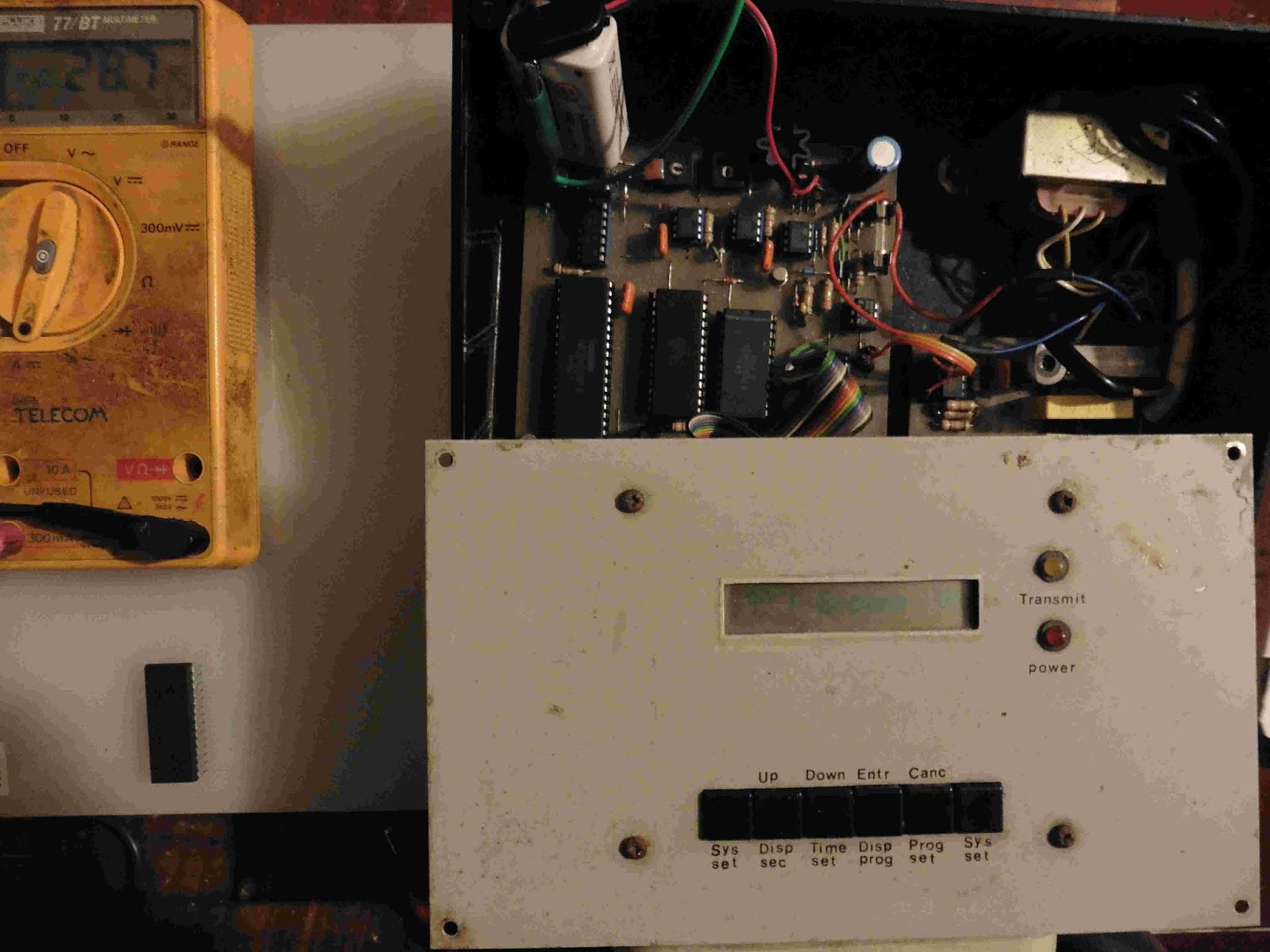
Below is a series of pics showing the combined current being drawn by the RTC controller from a 9V rechargeable battery.  I start off with 'known-quantity' eproms, those I have had for decades and most likely bought from Cricklewood Electronics, London.  The first one is a non-CMOS 27128, this draws about 60mA.  Next in line is a genuine CMOS 27c128.  This draws less than half the current of the previous one, about 29mA.  Next come the impostors, first a Chinese 27c64, which pulls around 55mA, followed by a 27c128, drawing nearly 60mA.  For variety, I've included a couple of EEPROMS, an Amtel 27c64 and a Xicor 28c256.  These almost certainly Chinese knock-offs, at least seem CMOS in nature, both drawing around 30mA.

What pisses me off is that I've gone from having what I considered a 'plethora' of eproms, to having about 3 that perform to specs.  It would be 4 but for the fact that I UV-wiped my one genuine 27c64 during the last (and final) edit of the RCT s/w, and it never recovered - not all bits would reset.  Which means I will also have to go looking for more, this time from a reliable source.

Edit:
The plot thickens.  Things are less straightforward than I thought.  First, the original 16KB Oric ROM has pin 27 labeled O/E (output/enable), whereas it's the PGM (programming) pin on 27128 eproms.  Since the Oric's Microdisk controller's ROMDIS (Rom-disable) is directly tied to this, it should explain perfectly why an Oric-1, hooked up to a Microdisk floppy-drive system, will not boot.  The complication arises with my Atmos, which I modified (decades ago!) to work with eproms, so that I could upgrade from the original buggy & slow v1.0 Basic, as I explained above.  So presently, I am still at a loss as to why these Chinese eproms will not work with my Atmos/floppy-drive setup.

Edit1:
Stranger & stranger.  I've just realised that my unmodified Oric-1, with the Microdisk floppy-drive attached, and fitted with my 'magic' eprom (TMS27c12820JL), will boot & run perfectly!  This makes no sense whatsoever!!!  This eprom was bought & flashed in the 90's.  Since the modified Atmos, and the unmodified Oric-1 operate perfectly with it, and the Microdisk attached, it stands to reason that something nefarious is afoot.  Seriously, should be impossible.


12 October 2019

Kingavon Gas Heater: Faulty regulator - an easy fix...

 Though it's mainly oil that's used for heating here, almost 2 years ago, I invested in a 'Kingavon' gas heater to heat my 'workshop'.  This has received scant use in the intervening time, mainly because of the way it wreaks havoc with my sinuses when it's running.  So in 2 years, it has consumed just two 11.xx kg cylinders worth of gas.  Three, if you include the one-third full one that's presently hooked up to it.

  Well, a couple of weeks ago, I decided to fire it up, only to discover that there was no gas being released.  I contacted Calor and was advised by a rep. that it was probably the regulator, and suggested that I might order a new one at the link they provided.

  Up till that point, I didn't even know that this was the regulator, having instead had a go at loosening couplings within the heater itself!  Anyway, all told, that was going to cost me €22 to replace, and as the Rep. had pointed out, there was no guarantee that that would fix it, and that maybe I should instead seek out a professional.  While pondering this dilemma, and with nothing to lose, I decided to attach an air compressor to the regulator's output - the narrow 'pipe' thing in the above pic - and was delighted to discover on reconnecting it to the heater, that it was working again.  Hurray!!!

  So, a quick post for a (possible) quick fix for someone encountering the same situation.

Edit:
  Well, this had worked, sort of anyway.  Gas had been released, but not at the rate necessary to fire up even one 'heater-section' properly.  I therefore went at it again and gave it a proper going over with the air-compressor, then attached a small vacuum pump to the outlet for good measure - which killed gas output completely!   Undaunted, and as a last resort, I air-compressor'ed the arse out of it, this time, including the regulator's input.  Wee, I had gas output again!  But after15-20min, the rate reduced, until one section would barely stay lit..  I guess I'm stuck with having to purchase a new regulator.   Heavy sigh.

Edit2:
  Cracked it!  While the compressed-air did 'something' to resurrect the gas regulator, just a couple of minutes after it was lit, the gas throughput was never close to what could be deemed normal - for instance, after 5-10 min, it would slowly undergo 'gas-starvation'  and the pilot flame would eventually go out.  And that's with just one bar lit, switch on more than one and it would go out almost immediately.

  So, with nothing better to do, I decided to heat up the regulator with a gas torch!  Sounds a more aggressive move than it actually was - my butane torch is just a little thing!  So after removing the plastic rain-protection cap, I spent about 5min getting it nice & toasty, then let it cool.  Result? - one perfectly working gas regulator!  It's being running for a couple of hours over the last two days without a problem.  So, Yay for me!

Edit3:
  Almost one year on, I've just had to eat crow and fork out for a new regulator.  The "fix" proved to be frustratingly variable in nature.  One day I'd get the expected gas output from it, another, it could be a reduced gas output or none at all.  Even when it was 'normal', the gas flow would invariably peter out after an hour or so of operation.  Despite this unsatisfactory situation, I would probably have continued on in this way for a while yet but for a recent 'occurance'.

 I happened to come across an old regulator lying about in a neighbours barn and borrowed it to establish once and for all that my regulator was faulty.  It was an old model, something that I remember seeing being used by relatives/neighbours in my youth.  I hooked it up to the cylinder, fired it up, and confirmed my suspicion - there was plenty of gas being output, causing one of the 'bars' to quickly redden - too quickly as it happened!  I immediately noticed that there was an excess of gas being released,the top of the lit-bar having a flame 2-3cm rising above it like a candle.  I then figured that the smart money would be on switching on another bar, thereby dividing the gas output between the two, mitigating somewhat the 'surplus gas' problem.

 What actually happened was that the flame-front traveled right back to the old regulator!  In an instant I had a 30cm flame squirting straight up from the top of the obviously faulty regulator, and a moment on, a smoke detector screaming for attention.  I managed to kill the flame by flicking the old-style regulator switch to the off position - or at least I think I did, it's all a bit of a blur.  The possibility of the flame having made it past the regulator and into the cylinder itself is what freaks me out.  Just how close was I to a gas explosion and a smear on a bedroom wall I wonder?

 On the bright side, there are worse ways to go I suppose - with a full cylinder of gas, at least it would have been quick! :)  I also got the new regulator today, which works as expected, though I'm no longer as blasé about gas heating as I used to be...

Edit4:

  Calor just keeps on giving & giving - but only frostbite and misery, as far as yours truly is concerned anyway.

 Unbelievably, the second, brand-spanking new regulator that I ordered from them has failed in an identical manner to the first one and in pretty much the same time-frame - it lasted only 9 months!!!

 The purchased regulator worked perfectly - until it didn't - one minute I could happily have all three 'bars' lighting, next, not even a single 'bar' would remain lighting.  Worse, I managed to use only 3 gas refills before this deplorable state of affairs reasserted itself.  Just how difficult can it be to design a regulator that  works?!?!?!?  Ironically, I have found that if I disconnect the regulator and leave it sitting on the oil-fired central-heating's radiator for a few days, it provides a temporary fix sometimes - about 1 hour, before the heater once again starts spluttering from gas starvation. 

 Anyway, I contacted Calor, fully expecting to hear that the 'new' regulator was also no longer in warranty, but instead learned that it had a 5-year extended coverage - YAY!!! - and that they'd send me out another one.  I next received an invoice for a new regulator from Hamilton Gas Products, who no doubt Calor sub-contract, followed by an email from Calor themselves, saying that a new regulator was on the way.

 That was more than a week ago, still no regulator!  Looks like it's going to be a 'Cold, Cold Christmas without...' Calor.  Sigh.

Edit5:

Weee, the regulator finally arrived and unsurprisingly, it works as it should (see pic.)  Also note perched on top of the heater, the other unblemished-but-faulty regulators.  It's more than a little disconcerting that the newly arrived regulator seems identical in every respect to the faulty ones - 1 going faulty could have been put down to bad luck, 2 faulty, especially in the same time-frame, it's more likely to be down to a bad design - but I hope I'm wrong!


5 September 2019

Chinese Mains Transformer QC also non-existent.

Another piss-and-vinegar post from me.  In the last post I alluded to the fact that I was having mains transformer issues with my RCT builds.  Here, I'll air my grievances.

More than a year ago, after having decided to construct two more remote switches, I quickly made a list of the parts required and shot off half a dozen orders to Ebay.  One thing I could not source on Ebay was the needed mains transformers, which was the reason that, despite proclamations in earlier posts, I ended up going back to Aliexpress, tail firmly between legs.  Although Ebay would be nothing without Asian Sellers, many more of these Sellers only seem to sell their wares through Aliexpress.  Anyway, transformers were ordered and promptly delivered.

Only, I had ordered the wrong ones!  At the time, I took a quick look inside my one remote switch, had seen 6v written on the transformer, so ordered two of the 220v @ 6v variety.  Only many months on, when I had finally received the PCB's from JLCPCB, and had started building, did I realise that what I needed was 12v transformers, not 6v, to power the 12v relays, and that the transformer in my working unit was in fact supplying 12v - 3-wire 6v-0v-6v.  Duh!  Unperturbed, I went a-searching on Aliexpress, found the correct transformers, or more accurately, the same spec 220v @ 6v-0v-6v transformers used in my working unit, but at less than half the price of what I had paid first time round, so shot off another order.  These also arrived quickly and seemed fine apart from the fact that there was adhesive all over the wires, probably that used to secure the iron core laminations, plus said leads were a little shorter than I would have liked.  But hey, I'd gotten them for half the price, so no biggie.

On connecting one up to my build under construction, what immediately became apparent was that, although they 'worked', you could hear that the 12v relay was being switched 'hard-on'.  Measuring the voltage across it while energised, I was shocked to see that it was over 18v DC.  De-energised, that rose to almost 20v.   The voltage across the 6v - 6v wires of the secondary was 16.4v AC, not the 12v AC that I was expecting.  Note that this is on a 240v mains supply, nominally around 238v, though the extra volts don't significantly change things.

I wasn't happy with this in the least, even after I realised that the relay would happily trigger when I used the 6v - 0v wires, therefore working from just 8.6v DC, I concluded that the 'cheapness' of the transformers was the culprit.  Particularly after checking the first 220v @ 6v transformers purchased and finding that they provided a reasonable 6.5v AC on their secondaries.  So, back to Aliexpress I go and order another 2 'expensive' transformers from the original seller, this time, 220v @12v, 2-wire, in the fervent hope that these would provide the expected voltage.

They didn't, and I'm pissed!!!

Below are a series of pics taken of measurements from the various transformers in play.  To be as unbiased as possible, I am powering them from a variac, supplying 220v AC.


Below are the voltage measurements taken from the working unit, but with the transformer in-circuit.  The first shows it being supplied from the variac @ 220v AC. The circuit is being powered (@ 15mA's), though the relay is not energised.  The secondary of the transformer sits at 11.47v AC.


Here I adjust the variac to provide 240v to the circuit.  The voltage increases to 12.27v AC, which had me wondering if these particular transformers, bought from Maplin (RIP) almost 30 years ago, were specifically manufactured in/for the UK.  Regardless, these are the voltages I expect to see from a 12v transformer, not some 3+ volts over the stated RMS value.

Finally, Also shown below are measurements across the transformer's secondary with the relay powered on & off, to show loading effects.  The maximum current drawn from the secondary by the PCB is 75mA AC.


Edit1:
Been playing with my scope's Save/Recall function, and aided by Linux's ever-versatile Gimp, grabbed waveforms & measurements from the 3 offending transformers, on the mains supply, and shown below.


Edit2:
Given the lottery that seems to be involved when buying transformers from China, I instead decided to try dismantling one of the 220v @ 12v 2-wire ones, to see how difficult it would be to adjust the turns-ratio of its secondary.  I had low hopes going into this - I figured there was a 70% chance of screwing it up entirely - instead, it proved to be surprisingly easy!

This was the first transformer I'd taken apart in this manner.  The wire to be removed from the secondary I calculated as follows;

19 Ohms (actual secondary resistance) - 12v (desired volts)  / 14.98v (actual volts) * 19 Ohms = 3.76 Ohms.

This is the resistance of the wire segment that needed to be removed.  I then used this Round Wire Resistance Calculator site to determine the length of (0.17mm) wire that would have a resistance of 3.76 Ohms - turned out to be a little over 5 meters.  After removing this amount and reassembling, I was pleased to find that its voltage after rectification, with the relay de-energised, had dropped to a much 'safer' level of 15.9v, one that wouldn't pop my 16v 220uF reservoir capacitor over time - the voltage had been over 19v in the 'relay-off' state.

However, the values I had used in the above calculations had been with a 220v supply, not the 240v I will actually be using.  So, working on the second 220v @ 12v transformer, and re-doing the above calculation with 15.8v as the 'actual volts', gave me a 'wire length to be removed'  of 6.175 meters. After doing so, i was presented with an RMS value of just over 13v AC on the secondary, which, in-circuit, rises to no more than 15.1v DC.  With the relay engaged, it actually drops to around 11.5v DC.  So, yay, I'm happy with this result.

2 September 2019

Hozan: Manufacturer of True 'Precision' Tools...

I bought my first 'proper' workbench tools over 30 years ago, a snips/cutters and a Snipe-nosed pliers, from Cricklewood Electronics, made by the prestigious German toolmaker C.K.  They cost a little over £10 each, way back then.  Despite the decades of abuse, these performed admirably, or at least one of them did - the first snips I destroyed within a few years, trying to cut something way beyond its pay-grade.  Lesson learnt, I immediately went out and bought another, and it's still in use today.  The original pliers, withstood three decades of similar abuse, but recently, heedless of past misdeeds, and being employed in a really dumb task, I managed to break this as well.  I was distraught.

But looking to get back on the horse as quickly as possible, I went searching for a replacement, and was elated to discover that Amazon sells the exact same pliers, though costing considerably more - almost £27 then, though the price continues its upward spiral, it currently costs £33.  But I was content to pay a premium for a tool of this quality.

Until receiving it anyway!  Examining it, it was immediately apparent that, in my opinion, the "C.K Classic T3772 120mm 'Precision' Snipe Nose Pliers", did not live up to this description.  I would have thought that the workmanship of tools made today would at least meet the standards of those produced by the same manufacturer more than 30 years ago - apparently not!  Although the jaws themselves were fine, where the two pieces hinge, there were large gaps, more than 1mm in places, and on both sides.  A side-by-side comparison with its much older (and broken!) sibling, highlights this (see pics).


Though some might accuse me of being pedantic, this was not acceptable to me, so back it went to Amazon.  I hoped my negative review about it on the site would at least have garnered a response from a C.K Rep, as C.K themselves are the Seller, but it was not to be.  Apparently, this level of 'Precision' is now the accepted norm in Germany.

All of this transpired back in February, so over 6 months ago, and I was still without a proper pliers for my bench-work.  So it was time to go shopping again, but this time I thought I'd give Ebay a try.

On searching, it became clear early on, that the Japanese company Hozan was one of the main contenders where quality tools were concerned, to the point that many Sellers, reassuringly all Japanese, post pics on how to spot forgeries.  One of these tell-tale signs was precisely the reason I returned the C.K pliers - poor manufacturing tolerances at the hinge-point.

Although I really only needed a pliers, as the C.K side-cutters is now quite blunt, I figured I may as well treat myself to a new snips as well.  Then I went completely mad and bought another, much more expensive, 'pulling-pliers' - or at least that was its intended use, to facilitate the removal of say, 8 to 14 pin i.c's.  Turns out the 'pliers' is actually a cutters and too small for extracting anything above 8-pin i.c's anyway, so it probably won't see much use.  All told, these cost $21 (snips), $27 (pliers) and $37 ('pulling' pliers) respectively.  See pics.

But, and the main point here, all of their 'tolerances'  are superb!  The fact that they are all 'spring-opened', rather than using a leaf-spring like the C.K tools, is a bonus in my eyes.  This is what I expect to see from quality 'Precision' tools.

So despite my having had a long history with C.K of Germany, I have reluctantly had to switch to a manufacturer that seems to care about the quality of the tools that they manufacture.  In my eyes, Hozan fits the bill on this count.  It's just a  shame that a long-established company like C.K seems to have become complacent with the passing of time.


10 August 2019

Chinese BC108B Transistors (TO-18): non-existent QC in play...

As part of my 'RCT Revamp'. I've been slowly accumulating the bits needed to build two more Remote Switches, to complement the single unit that I had originally built.  But that's for another post, this is about the BC108B transistors needed that I sourced & bought through Aliexpress - and yes, I'm back buying stuff from this lot again!

After getting my PCB's from JLCPCB - so much easier than messing with ferric chloride, like I did originally! - I soon had one (1 of 5) populated & ready to rock.  Except it didn't work!  Checking the 6 BC108B transistors with a multimeter, I discovered that one was completely open - all B-C-E connections, which seemed decidedly odd.  All the others tested fine.  Swapping out the dud with a new one didn't solve the problem.  I then went off on the wrong tack and ended up destroying two UM3750's, the decoder chip used, which apparently are really finicky about the voltage level applied to its input.

Long story short, with my one working (old) unit to compare against, it soon became apparent that there was something amiss with the transistors I was using.  Starting afresh with a new PCB (2 of 5), and taking measurements as I built, I soon realised that the transistors were not 'amplifying'  the superimposed 200Khz signal from the mains.  Removing all four that I had soldered in, and checking their gain with my trusty old meter, I was shocked to discover that their gain (hFE) ranged between 0 to 107, far from the 200 minimum that these transistors are rated at.  The last two unused transistors were also checked, these came in at 84 and 102 respectively (see pics).

This got me to wondering about the 100+ other Chinese transistors that I've got, which are all of the TO-92 variety.  These as it happens, seem to be perfect, each batch of the same transistors measuring respectable hFE's, and within shouting distance of their compatriots.

So it seems that only the TO-18 type BC108B's that I've bought are crap.  And they were not particularly cheap either!  The reason I ended up ordering them from Aliexpress was that they are considerably more expensive when ordered from Ebay sellers.  But what I got is garbage, which is compounded by the fact that I ordered another 20 of them (from a different Aliexpress seller) [after checking, it's actually an Ebay Seller] before I discovered the hFE problem.

It would appear incredibly unlikely that the 'ST' branded BC108B's  that I got are actually manufactured by STMicroelectronics, instead being produced by some knock-off outfit that employs zero Quality Control testing.

I've being playing with transistors for 40+ years and admit that I had never before come across a transistor with zero gain.  Or 32 for that matter.  Out of the 15 transistors I ordered, only 2 came close to the expected 200 gain (213 & 187).  These two can be seen soldered in-situ and that portion of the circuit (now) works as expected.
 
Edit:
I removed all six BC108B transistors from the first PCB (1 of 5) today, to check their gain.  As expected, the highest gain measured was 102, with one coming in at a mere 10 - so, it's understandable that this RCT build wasn't working!  I figured though that the one 102-gain transistor would work ok in what I deemed a 'non-critical' part of the circuit - wrong!  Removing it again and replacing it with a 187-gain TO-92 transistor, had the circuit working perfectly.

Now all I need to do is triple-check the changes I have made to the PCB layout and re-submit them to JLCPCB.  Although the original batch (of 5) work fine, given how cheap they were, I didn't bother adding mounting-holes first time round, as I was sure that there would be other issues that would be discovered during the build-process - there were, but mainly minor things like component placement & hole-sizes, that need altering.  I am also taking the opportunity to add a single component of my own to the circuit, a 5.1v zener diode, to squish a nasty transient spike, on one of the 'SET' pins of the 74LS74, which is generated during switching, and only discovered today.  Even though it spikes to almost 9v, so well above the 5v operating voltage, the original RCT unit's 74LS74, suffering from the same condition, [maybe not... after checking, it spikes, but less than a volt, odd...] is still working after nearly 25 years, so yeah, a non-critical addition.  But on the off-chance that it might cause occasional false-triggering, I may as well fix the problem.  

Edit1:

Update.  Just received my new order of 20 BC108B's.  Testing, first four out of the bag had me questioning my new-found beliefs about Chinese QC - all 4 had an hFE >= 200 - unfortunately, this run of luck was not to continue.  All told, 10 proved to have gains greater than 200, 4 were less than 170, 3 less than 100 and another 3 less than 50.  A crap-shoot basically!  Even the hFE > 200 varied wildly, with gains ranging between 200 and 700, although admittedly, most were around 200.  So I guess it's up to the buyer of cheap tat like this, to first test, then keep the best & bin the rest.

Luckily, I've now got enough BC108B's of the TO-18 variety to populate the two planned RCT PCB's.  All that's preventing me from continuing is needing to reorder PCB's from JLCPCB, receive the (right!) transformers, and... laziness.


4 February 2019

Remote Control Timeswitch - Olde ETI project revamp...


And now for something completely different... besides the bitching & moaning that is normally my forte, as I'm sure I'll find plenty to gripe about here as well.

I came across & built this project from the long defunct magazine, Electronics Today International (ETI) way back in the early 90's - so yeah, I'm getting on a bit!

I loved the concept behind it from the get-go - superimpose control signals onto the mains supply, that could then be intercepted & acted upon by Remote Switches.  I also loved the fact that I'd be building from scratch, my own 'real'  computer - CPU, RAM, ROM, programmable input via the 6-button keypad, output in the form of the control signals that were being superimposed onto the mains and finally, a nice LCD display to program it with.  Yes indeed, a real computer!

The building of it was laid out over 3 issues (1,2,3), and the firmware was available free of charge for the price of a SAE direct from ETI themselves.  Construction itself was fairly straightforward, at least as far as getting it up and running.  The firmware was tapped labouriously into a Sinclair Spectrum 48K, which was then used to burn a 27C128 eprom via a home-made eprom programmer board stuck precariously on its backside.  In fact, this was my first experience with eproms and I actually bought new, specially for this project, the gear required for this, and which I still possess - 2 'black-light' tubes for developing light-sensitive PCB's, 1 UV tube for erasing the eproms, along with the necessary mains transformers to drive them.  These I got from two nice old guys somewhere in London, both of whom are unlikely to be still with us, rest their souls.

Anyway, build it I did, and work it did, at least to a fashion.  What immediately became apparent, was that the software was buggy - incredibly buggy as it happened!  For instance, the unit was incapable of operating for more than a day or so before resetting itself, which resulted in all of the time settings, as well as the time-switch programs, being wiped.  There was also the miriad of 'Power failure detect' messages that it randomly displayed, even when on battery power, that suggested that something was awry.

It had hardware problems as well, one of which I have only just discovered, much to my chagrin.  The first involved the pulse-width of the 50Hz pulses that were being derived from the mains.  This was solved by piggy-backing some additional circuitry onto the i.c. involved.  The other concerned the crystal oscillator.  For going on thirty years, I had always presumed this to be above suspicion.  Recently however, the unit stopped working entirely, so after a brief scope-check, I concluded that the crystal had 'finally' died, so ordered a new one.  I highlight, 'finally', 'cos at least 20 years previously, I had noticed on a crappy old Gould analogue oscilloscope that the frequency 'appeared off'.  I put that down to the crystal also about to expire way back then as well!  On swapping out the crystal with a new one, I was puzzled to find that it still would not power on.  Checking the frequency, I discovered that it was well over 10 Mhz - the LCD/keypad-i/f was only capable of operating up to 3 Mhz.  A quick google, soon revealed the problem - with the component values used, what you had was not a crystal oscillator, but a RC oscillator.  In fact, the RC values used completely negated whatever effect the crystal might have had, oscillating at the RC frequency whether or not the crystal was even in the circuit.  Using 'sane' values, I soon had an oscillator which produced a beautiful 1.8432 Mhz square-wave - probably for the first time ever!

But that was a present-day discovery.  Jumping back 25 years, the real problems all seemed software-related.  The firmware as it stood, simply didn't work, so I had the option of tossing everything into the bin, or debugging the software from scratch.  The latter was obviously the chosen route, and much to my surprise, it took only about a week or so.  I ended up with 8-10 pages of commented z80 code, removed all of the 'fatal' bugs, and discovered & removed 3-4 less obvious ones.  A problem I discovered several years on from this, was that, as it stood, the original code did not correctly 'form' the control-codes that were being sent out over the mains.  These codes determined which remote-switch was to be activated, the problem being that, say remote-switch number-4 was transmitted, remote-switch number-8 could end up being activated - so, not good!  As the entire remote-switch number generation is done via software, this proved a real pain to fix, as it meant that about a dozen eprom erase-burn cycles were necessary before I got it working properly.  What I wouldn't have given for an in-circuit eprom emulator way back then!

The one other real obstacle to fixing the firmware proved to be finding 'space'.  The original code takes up 4092 of the maximium readable (by the CPU) 4096 bytes of memory - an extra address line would have made things so much easier!  So, every time I needed to change something, I invariably had to first go and optimise the original code to gain a few more precious bytes.  This proved relatively easy initially, but it has gotten to the point where a very large percentage of the subroutines have been altered.  I was eventually reduced to merging individual subroutines in order to limit the number of 'push', 'pop' and 'ret' instructions that were needed.

Anyway, apart from the bug-fixes, and two little 'additions', the original firmware's functionality is still wholly intact.  The additions are keypad-related.  1) With the backup-battery connected, it is necessary to physically open the unit (or wait 20+ hours for a Li-ion battery to die!) in order to issue a reset - real tedious!  Now, by pressing both 'Sys' keys, the 'Down' key and the 'Entr' key simultaneously, while in 'Clock-mode', the system will be reset.  2) In Setup-mode, to facilitate calibration of the Remote Switches, the unit will normally send 13 'frames' to signal 'On', and 11 frames to signal 'Off'.  However in 'normal-mode', the number of frames sent is 16 for 'On' and 8 for 'Off'.  Now in Setup-mode, when the Xon/Off option is selected, by pressing the 'Down' key and the 'Entr' key simultaneously to initiate the sequence, the unit will instead use 16 & 8 frames when switching.  Number 1) in particular requires a 'knack' to pull off - all keys must be pressed simultaneously - but once achieved, it's easy from then on.

There are a couple of other vexing hardware related problems with this design.  One is that while the battery 'trickle-charge' circuitry does work, it will eventually result in the battery being destroyed, due to constant charging.  I've  been through several already.  The other problem almost defeats the entire raison-d'etre of the device.  Sometimes, after a power-cut, when power is restored, switching noise will cause the unit to reset itself, losing all stored programs.  I'll try to find solutions to these problems and post updates here eventually, hopefully it won't take another 25 years!  The original firmware, along with my final revision, is available here for download.

Finally, a word out to Mr Kevin Browne if he's still with us - Thank you for giving us this interesting project way back then - it's kept me interested anyway!

Edit:
A couple of months on, the unit is still on my work-bench, on test, its innards exposed.  I was intent on fixing the battery-overcharging problem with the aid of a small DC-DC converter - over-kill, I know -  and even ordered a few on eBay.  All for naught as it turned out.  Using a 9V Li-Ion battery with inbuilt protection is all that's needed, as its circuitry will electrically disconnect the battery when it is fully charged.  At least the ones I have from manufacturer Soshine do (good batteries, but take their advertised capacities with a pinch of salt!).

The resetting on power-recovery issue seems to occur only when the backup battery voltage is very low, around 6V, so should only be a problem if the electricity remains off for an extended period (15+ hours with the Li-Ion battery I'm using).

Finally, I found & fixed, hopefully the last 2 remaining bugs in the firmware.  Both were trivial display issues that didn't effect the unit's operation in any way.  One I was already aware of, the other, would only show itself if the maximum number of user-programs entered exceeded 255 - ordinarily, an impossibility, but zapped anyway.

Addendum.
While perusing my old collection of electronics magazines, I came across a follow-up article in ETI, a few months on from the RCT project, 'critiquing' the original work.  As I'd forgotten about it, I'll add it here for completeness, even though, imo, it was little more than a hatchet-job.

Several of the points raised by its author were frivolous, others without merit, while the rest are just plain wrong.  For instance, the radical notion of replacing the original regulated power supply circuitry (which works perfectly!) with a 7805 is ridiculous, if only from an aesthetic point of view. He also mentions swapping pull-up resistors, just a few K-Ohms in difference, as being necessary, and tying another pull-up resistor to ground, rather than to the positive rail - both incorrect!  In short, almost all of the component choices selected by Mr. Browne work fine, including those used in the various frequency-adjusting circuits.

The one thing he got right involved the 50Hz pulse-width that I've already mentioned above, although just using a different value resistor proved insufficient in my case, as the pulse amplitude gets attenuated below 'logic-level 1'.  I chose to include an additional Schmitt trigger, feeding it's output to a pot/capacitor pair, which allows the required pulse-width to then be set with ease & precision.

Edit:

I've spent the last few days removing 2 more original bugs that I first thought couldn't possibly have existed and that I must have introduced - but having checked the original firmware in action, apparently not!  Both concerned Program-entry.  The big one required a 30+ byte workaround, which I initially thought an impossible fix, given the imposed 4096 byte limitation - but apparently not there too!  Most of the space was found within a particular subroutine that was trying to do stuff that wasn't even necessary, the rest of the savings came from re-coding from scratch some other routines.   The functionality still remains identical to the original firmware, with zero features having been removed.  2.5 years ago, I was certain I had eradicated all of the original bugs - now I'm even surer!  The updated firmware is available from the original link above :) 

 I forgot to mention, my relying on the Soshine 9v battery's 'protection-circuitry' didn't go according to plan.  The protection circuitry appeared to work fine - stick one on a crappy old 9v charger - the type with no proper voltage/current regulation, and it would disconnect itself electrically when charged.  However, I've only just noticed that my once new & unused Li-ion battery has developed a 'bulge' from what appears to be from being over-charged!  Worse, it's ability to hold charge has also been decimated, falling from around 450mAh to a miserly 180mAh  - and all because of my laziness.  It still manages to power the control unit for 9-10 hours (down from 21-22hrs when new), so things could have been worse.  Maybe it's a result of all the power-cuts we experience around here - once the power reconnects, it will recommence charging.  Anyway, here's hoping this alleviates the problem...

 As a result, I've finally wired in a little circuit to limit the applied charging voltage to 8.4v, just 3 connections needed, with the 2 power-lines slotting in where R10, the current-limiting resistor used to be, and ground.  Better late than never!  Made up of a transistor, zener and a couple of resistors.  Works ok, although the little bc108 transistor gets a bit toasty when charging the battery from flat - hits around 75DegC. - even so, the supplied current never goes above 60mA.

One other little discovery I've just made concerns the remote switches.  Both of the two new builds have proven frustrating to get working properly, and though it should come as no surprise (to me), it's all been a result of those shitty bc108's from China.  This realisation came the other day while working with one unit, whose performance was abysmal.  Almost as a last resort, I swapped out the first 2 amplifiers, both of whose hFE's were in the 400 range, with 2 whose gains were just over 140 - yep, I was really grasping at straws!  Unsurprisingly, I ended up with a door-stop!  In one last final act of desperation, I swapped out the 1st input transistor again, but with a replacement that sported a gain of over 700.  The result was profound.  My once-barely-functioning switch is now by far the best of the three, reliably switching in remote parts of the house where none of the others will even operate.  Alas, it was my one-and-only 700+ transistor - despite checking well over 100 'Chinese' transistors after the 'discovery' - so at present I don't have the means to see if this 'fix' would work in the other switch as well.  I had & tried a bc108 that had a measured gain of 'just' 500+ ( the old one having been 400+) but it still won't operate from the 'remote' location.  

I'm really going to have to source some genuine bc108/9's somewhere.  While I realise that 'in-spec' bc108 (and BJT's in general) gains are all over the place, the alarming number of sub-100 gains that I've got through Aliexpress gives one pause for thought.  Given my recent post regarding the 2n3819 FET's that I ordered & which turned out to be NPN transistors, right now I feel like ordering from China is no longer an option.  It's one thing to be taking a chance and ordering out-of-spec components - like the bc108's I received seem to be - it's another thing entirely when they're labeling transistors as FETs.